Software architecture with C4 model
C4 model is a lean graphical notation technique for modeling the architecture of software systems. It is based on a structural decomposition of a system into containers and components and relies on existing modeling techniques such as the Unified Modelling Language (UML) or Entity Relation Diagrams (ERD) for the more detailed decomposition of the architectural building blocks.
The C4 model was created as a way to help software development teams describe and communicate software architecture, both during up-front design sessions and when retrospectively documenting an existing codebase. It's a way to create maps of your code, at various levels of detail.
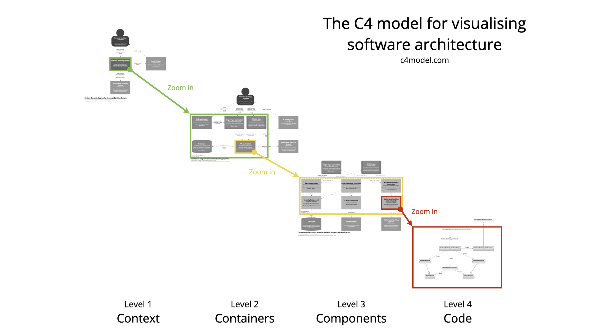
There are four types of C4 models, each one for a different audience and containing a different level of detail. These are the context, container, components, and code diagrams that make up your software architecture model.
Level 1: Context Diagrams
Context diagrams are the most general description of what your system does, who will use it, and what other systems it will interact with. A context diagram will help you describe the scope of your project and help you pinpoint who the user is and what problem you’re going to solve.

Level 2: Container Diagrams
The container diagram takes the first step into describing the software system and shows the APIs, applications, databases, and microservices that the system will use. Each of these applications or services is represented with a container and the interactions between them are shown at a high level.

Level 3: Component Diagrams
One step deeper than the container diagram, the component diagram details groups of code within a single container. These components represent abstractions of your codebase.
This diagram type is comparable to a UML component diagram but follows a less-strict set of “rules” in order to create the software architecture diagram.

Level 4: Representing Code with Class Diagrams
The last level requires lots of detail to show how the code of a single component is actually implemented. To do this, you would want to make a UML class diagram or entity relationship diagram that describes the component.

For more diagrams and notations, c4model.com